** TGS»çÀÌÆ®¿¡¼­ º¸½Ç ¼ö ¾ø´Â DATA SHEET´Â ¹é¹üÀüÀÚ(ÁÖ)·Î °³º°¹®ÀÇ ¹Ù¶ø´Ï´Ù.

Tantalum Capacitors

CA42 Series Epoxy-Coaled Solid Electrolytic Tantalum Capacitor
 
 
Brief introduction
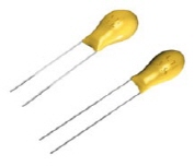
CA42 Series sinter--anode, epoxy--coated solid electrolyte tantalum capacitors
are encapsulated with flame-retardantyyellow epoxy powder, marked with laser.
CA42 Series meets and exceeds the requirements of IEC Specification 384-15-3,
IECQ Specification QC300201 / US0003 and Technical; Specification SJ/T0806-96,
used in military and civil application such as TV sets, camcorder, computers,
Program controlled electronic telephone switching systems, telephones, instruments
and meters.


Features
 
♠ Operating temperature range : -55¡É ~ +125¡É ; £¾85¡É with rated voltage derating.
♠ Rated Voltage : See Table 1
♠ Dissipation factor at 20¡É : Please see Table 3
♠ Capacitance range : 0.047§Þ - 680§Þ, see Table 1
♠ Dissipation tolerance : ±20¡É ; ±10¡É ; ±5¡É (for special order)
♠ Case sizes and dimensions, Please see Table 2
♠ Temperature characteristics : See Table 3
 

Rated Voltage, Nominal Capacitance and Case Sizes

 
  Table 1-1
 
Rated Voltage(V)5 3 4 6.3 10 16 20 25 35 50
Voltage Derating(V) 2 2.5 4 6.3 10 13 16 20 32
Surge Voltage(V) 4 5.2 8 13 20 26 33 46 65


  Table 1-2  
 
Capacitance(§Þ) Case size
0.047               A A
0.068               A A
0.1               A A
0.15               A A
0.22               A A
0.33               A A
0.47               A A
0.68               A A
1         A A A A B
1.5         A A A A C
2.2       A A A A B C
3.3     A A A B B B D
4.7 A A A A B B B C D
6.8 A A A B B C C D E
10 A A B B B C C D E
15 A A B C C D D E F
22 B B C C C D D E F
33 B B C D D E E F  
47 C C D D D E E F  
68 D D D D E F F    
100 D D E E E F F    
150 D E E E F        
220 E E E F          
330 E F F            
470 F                
680 F                

¡ãtop

 
Dimensions Millimeters 
     Table 2  
  
Case Size D ( max ) H ( max ) H ( ±0.5mm ) d ( ±0.5mm )
A 4.5 7.0 0.5 0.5
B 5.0 8.0 2.5 0.5
C 5.5 9.5 2.5 0.5
D 6.5 11.0 2.5 0.5
E 8.5 13.0 5.0 0.5
F 9.5 16.5 5.0 0.5
 
Temperature Characteristics
  Table 3
 
Capacitance (§Þ) Cap Change ( % ) DF Max ( % ) DCL Max ( §Ë )
-55¡É +85¡É +125¡É -50¡É +20¡É +85¡É +125¡É +20¡É +85¡É +125¡É
¡ì1.0 ±10 ±15 ±25 6 4 6 6 or Io ¡ì
0.0 2CRVR1
§Ë *
10 Io 12.5 Io
1.5 ~ 6.8 8 6 8 8
10 ~ 68 10 8 10 10
100 ~ 680 12 10 12 12
*Whichever is greater
 
Packaging information
 
B : Bulk pack
 
A : Ammo pack ( per Specification IEC286-2 )
Designation Symbol Dimensions (mm)
Pitch of component P 12.7 ± 1.0
Feed hole pitch Po 12.7 ± 0.3
Tape Width w +1 ~ 18 ~ -0.5
Hold down tape width Wo 12 ± 0.5
Hole position H3 +0.75 ~ 9 ~ -0.5
Hold down tape position W2 1.0 max
Overall component height H1 32.5 max
Component alignment ¡âP ± 1.3 max
Feed hole diameter D 4.0 ± 0.3
Tape thickness T 0.5 ± 0.2
Component alignment ¡âh 2.0 max
Length of snipped leads L 11 max
Lead clinch height H 16 ± 0.5
Lead wire spacing S 2.5 ± 0.5 5 ± 0.7
Feed hole center to wire center P1 5.10 ± 0.5 3.85 ± 0.7
Hole center to component center P2 6.35 ± 0.4
Component height H2 +2 ~ 18 ~ -0
Lead diameter D 0.5 ± 0.05

¡ãtop

 
Lead Styles ( Other lead styles are available )
 

¡ãtop

 
Typical Characteristic curve
 
CA45 Series Solid Electrolyte Tantalum Chip Capacitor
 
Brief introduction
 
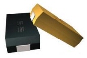
CA42 Series sinter--anode, molded solid tantalum chip capacitor,featuring small
size, high capacitance, high reliability and excellent operation performances,is
used for telecommunications, computers, camcorder, SMT electric circuits, and
so on. CA45 Series meets the requirements of EIA Standard 535BAAC.


Features
 
♠ Operating temperature range : -55¡É ~ +125¡É ; £¾85¡É with rated voltage derating.
♠ Capacitance tolerance : ±20¡É ; ±10¡É (for special order)
♠ DC leakage at 20¡É : Io ¡ì0.01 C£ÒU£Òor 0.5§Ë (Whichever is greater)
♠ Dissipation factor at 20¡É : Please See Table 3
♠ dimensins, rated voltage and nominal cpacitance : Please see Table 1 & 2 and Figure 1.
♠ Temperature characteristics : See Table 3
♠ ESR : See Table 4


¡ãtop

Outline Drawings
 

Dimensions Millimeters
Case size L ± 0.2 W ± 0.2 H ± 0.2 S ± 0.2 W2 ± 0.2
S 2.0 ± 0.2 1.3 ± 0.2 1.2± 0.2 0.5 ± 0.3 1.2 ± 0.1
A 3.2 ± 0.2 1.6 ± 0.2 1.6 ± 0.2 0.8 ± 0.3 1.2 ± 0.1
B 3.5 ± 0.2 2.8 ± 0.2 1.9 ± 0.2 0.8 ± 0.3 2.2 ± 0.1
C 6.0 ± 0.3 3.2 ± 0.3 2.5 ± 0.3 1.3 ± 0.3 2.2 ± 0.1
D 7.3 ± 0.3 4.3 ± 0.3 2.8 ± 0.3 1.3 ± 0.3 2.4 ± 0.1
E 7.3 ± 0.3ZM 4.3 ± 0.3 4.0 ± 0.3 1.3 ± 0.3 2.4 ± 0.1
 
Rated Voltage, Voltage Derating, Surge Voltage and Normal Capacitance
  Table 2-1
 
Capacitance Case size ( Standard / Extended )

0.1

        S   A A
0.15         S   A B/A
0.22         S   A B
0.33         S   A B
0.47       S S A B/A C
0.68     S S A/S A B/A C
1   A/S A/S A/S A A B/A C
1.5 S A/S A/S A/S B/A B C/B D/C
2.2 S A/S A/S B/A B/A B C/B D
3.3 A/S A/S A/S B/A C/B/A C/B D/C/B D
4.7 A/S A/S B/A/S B/A D/B/A C/B D/C E/D
6.8 A/S B/A/S B/A C/B/A D/C/B D/C D/C D
10 B/A B/A B/A C/B/A D/C/B D/C D/C E/D
15 B/A B/A C/B C/B D/C D/C E  
22 B/A B/A C/B D/C D/C D E  
33 C/B C/B D/C D/C D E/D    
47 C/B C/B D/C D/C E/D E    
68 D/C/B D/C D D E/D      
100 D/C/B D/C D/C D E      
150 D/C D/C E E        
220 D E/D E/D E        
330 E E/D E          
470 E              
 
Temperature Characteristics
 
Capacitance ( §Þ ) Cap. Change DF Max. DCL Max.
  -55¡É +85¡É +125¡É -55¡É +20¡É +85¡É +125¡É +85¡É +125¡É
¡ì1.0 -10 10 12 6 4 6 6 10 Io 12 Io
1.568 10 6 10 10
100-470 12 8 12 12
 
ESR of capacitor
 
Rated Voltage 4.0 6.3 10.0 16.0 20.0 25.0 35.0 50.0
Capacitance Case size ( Standard / Extened )
0.1         25.0   24.0 22.0
0.15         25.0   21.0 17.0/15.0
0.22         25.0   18.0 14.0
0.33         25.0   15.0 12.0
0.47       25.0 25.0 14.0 10.0/12.0 8.0
0.68     30.0 25.0 12.0/25.0 10.0 8.0/10.0 7.0
1.0   14.0/25.0 13.0/25.0 11.0/20.0 9.0 7.0/8.0 6.5/10.0 5.5
1.5 30.0 12.0/25.0 10.0/25.0 8.0/12.0 5.0/6.5 5.0 4.5/5.2 4.0/4.5
2.2 25.0 9.0/20.0 7.0/15.0 5.5/6.5 3.5/5.3 4.5 3.5/4.0 2.5
3.3 9.0/20.0 7.0/12.0

5.5/10.0

4.5/5.0/6.0 2.5/3.0/7.0 2.8/4.0 2.0/2.5/3.5 2.0
4.7 7.5/10.0 6.0/7.0 4.0/5.0/15 3.5/4.0 2.8/3.0/6.0 2.4/3.5 1.5/2.2 1.4/1.5
6.8 6.5/7.0 4.0/5.0/15 3.0/4.0 2.5/3.5/5 1.8/2.0/3.5 1.4/2.0 1.3/2.0 0.9
10 4.0/6.0 3.0/4.0 2.5/3.0 2.0/2.8/5 1.3/1.8/3.0 1.2/1.8 1.0/1.2 0.8
15 3.5/4.0 3.3/4.0 2.2/2.8 1.8/3.0 1.1/1.7 1.0/1.2 0.9  
22 3.2/3.5 2.5/3.5 1.8/2.4 1.1/1.6 0.9/1.2 0.9 0.9  
33 2.2/2.8 1.8/2.0 1.1/1.6 0.9/1.5 0.9 0.9/0.7    
47 1.8/2.2 1.6/2.0 0.9/1.2 0.9/1.4 0.9/0.9 0.6    
68 1.1/1.6/3.5 0.9/1.6 0.9 0.9 0.9/0.7      
100 0.9/1.3/2.5 0.9/1.4 0.9/1.3 0.9/0.7 0.5      
150 0.9 0.9 0.9 0.9        
220 0.9 0.9/0.7 0.9/0.5 0.9        
330 0.9 0.9/0.5 0.9          
470 0.9              
 
Tape and Reel Dimensions

Case size W Q'ty per reel
A B 1.50 8.4 0.00 2000
C D 2.00 12.4 0.00 500
E
2.00  12.4  0.00
400
S 2.00 12.4 0.00 2500
Case size A ± 0.2 B ± 0.2 C ± 0.1 E ± 0.1 F ± 0.1 W ± 0.3
S 1.5 2.4 4.0 1.75 3.5 8.0
A 1.9 3.5 4.0 1.75 3.5 8.0
B 3.1 3.8 4.0 1.75 3.5 8.0
C 3.6 6.4 8.0 1.75 3.5 12.0
D 4.7 7.7 8.0 1.75 3.5 12.0
E 4.8 7.7 8.0 1.75 3.5 12.0
Capacitor Markings
 
Direct designation is used for case sizes B, C, D, E while code designatios is used for case size A and S.
 
Rated Voltage Code
 
Rated Voltage 4.0 6.3 10.0 16.0 20.0 25.0 35.0 50.0
Voltage code G J A C D E V H
 
Capacitance code
 
Capacitance 1 1.5 2.2 3.3 4.7 6.8
Capacitance code A E J N S W
Multiplier 10^4      
Second digit        
 
Exp.A6C : Arepresents nominal capacitance code, the second digit represents multiplier and the third digit represents rated voltage, that is : voltage 16V: Capacitance 1*10 §Ü, 16V1§Þ
 
Characteristic Curve

¡ãtop